




 English
  Español
  русский


A 30-metre carbon-steel steam line heats up from 20 °C to 210 °C at every start-up. Fully restrained, that temperature rise would generate a thermal stress well over 400 MPa in the pipe wall — far beyond the yield strength of carbon steel — and the line itself would grow about 70 mm along its axis. The anchors, the flanges and the equipment nozzles cannot accept that. The practical engineering answer for a straight pipe run is an axial expansion bellows: a corrugated metal element that absorbs the longitudinal movement so the rest of the system stays within its allowable loads.
Selecting the right axial expansion bellows comes down to four numbers: required axial movement, design pressure, design temperature and expected cycle life. Get those right and a bellows can serve the line for decades. Get them wrong and you will be planning an unplanned shutdown within months. The sections below explain how an axial expansion bellows works, how to size it from basic thermal data, and where field failures usually start.
What Is an Axial Expansion Bellows?
An axial expansion bellows — also called an axial expansion joint or an axial metal compensator — is a flexible component installed in a straight pipe run to absorb displacement parallel to the pipe centreline. The core element is a thin-wall corrugated stainless-steel tube. Each convolution flexes like a small annular spring, and because the assembled bellows is far more flexible than the rigid pipe, almost all longitudinal movement is taken inside the convolutions instead of being transmitted to anchors and nozzles. These assemblies are used wherever straight runs need thermal compensation: steam distribution, hot water, heat-transfer fluid, cryogenic transfer lines and engine exhaust ducting.
A complete axial expansion joint normally includes the following parts:
- Bellows element — single-ply or multi-ply stainless steel (304/316L, or a nickel alloy for high-temperature duty) that provides the flexibility and contains the pressure.
- End connections — butt-welding ends, loose flanges or welded flanges, selected to match the existing piping class.
- Internal flow liner — a thin sleeve inside the bellows that keeps the flow smooth, reduces turbulence and protects the corrugations from particle erosion.
- External cover — a protective jacket for outdoor, underground or insulated installations.
- Limit or tie rods — used only in special configurations; a pure axial joint normally omits them so nothing restricts the movement.
Figure 1 shows the main parts in an isometric cutaway.
Figure 1. Main components of an axial expansion bellows (isometric cutaway).
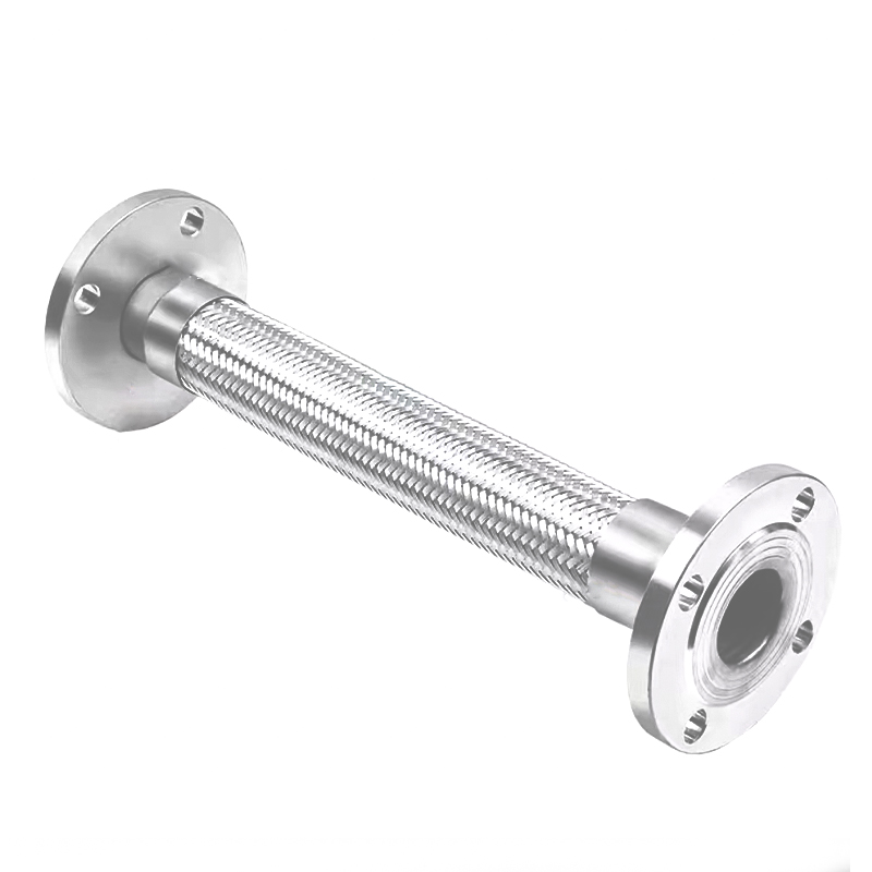
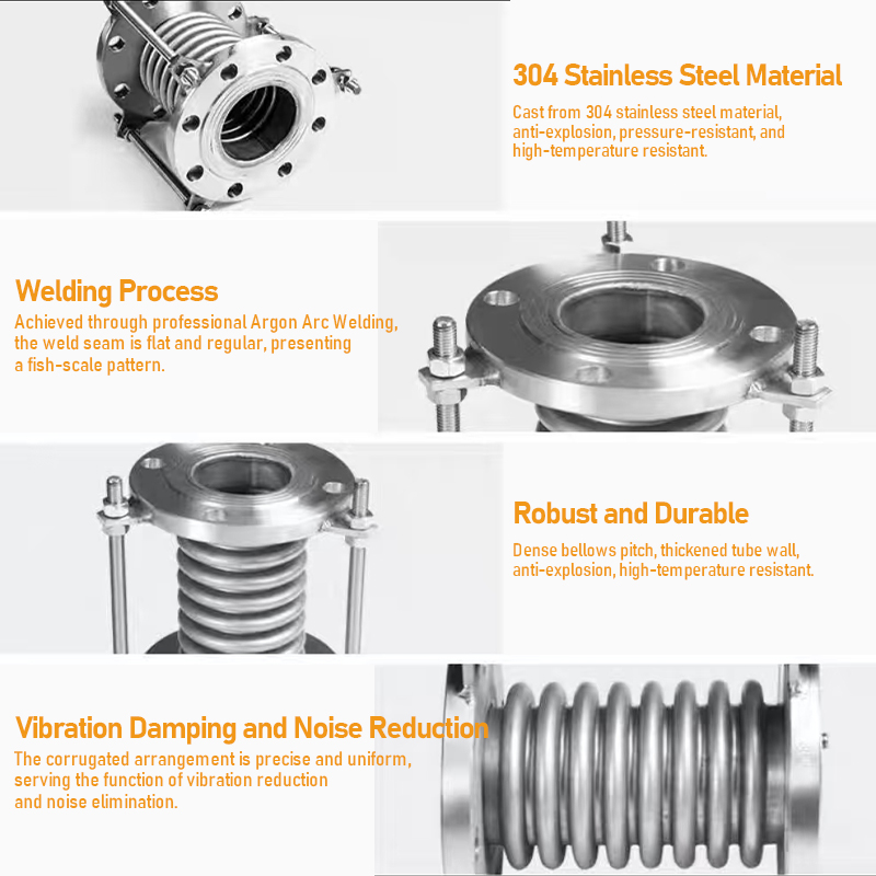 Flexible Metal Compensator Corrugated Expansion Joint with 304 Stainless SteelThis axial expansion bellows absorbs thermal growth in piping systems. Made from 304 stainless steel or carbon steel, it supports pressures up to 1.6MPa and suits water, steam, and oil applications.View Product →
How an Axial Expansion Bellows Handles Thermal Movement
Thermal expansion is a matter of physics, not opinion. The growth a bellows must absorb is calculated with the standard formula:
ΔL = L × α × ΔT
where L is the straight pipe length in metres, α is the coefficient of linear thermal expansion of the pipe material in mm/m·°C (for carbon steel, approximately 0.0123), and ΔT is the temperature rise in °C. The result is the axial movement in millimetres that the expansion joint must accommodate between two anchors.
The chart below gives the calculated growth for a 10 m pipe of common materials over a 100 °C rise. Stainless steel, for example, grows about 40 % more than carbon steel of the same length — a fact that matters when a line is converted from carbon steel to stainless without re-checking the bellows movement rating.
Figure 2. Thermal expansion per 10 m of pipe per 100 °C temperature rise, calculated from typical coefficients of linear thermal expansion.
The bellows absorbs this growth by compressing or extending along its axis. Its low axial spring rate keeps the reaction force on the anchors small, but the movement capacity is finite — which is why the next step is a proper selection calculation.
Key Selection Criteria: Movement, Pressure, Temperature, and Cycle Life
Once the required axial movement is known, it becomes the centre of the specification. The line chart below shows how quickly the demand grows: for a 30 m carbon-steel line, every additional 25 °C of temperature rise adds about 9 mm of required travel.
Figure 3. Calculated axial growth of a 30 m carbon-steel line versus temperature rise (α = 0.0123 mm/m·°C).
Movement
The calculated growth is the minimum capacity. Add a margin of at least 20–30 % for start-up transients, ground settlement and installation tolerances, then specify the rated movement as plus and minus values from the free length.
Pressure
Every bellows has a maximum allowable working pressure. When pressure is high, a multi-ply bellows provides more strength than a single ply of the same total thickness while keeping the spring rate lower. Avoid jumping to a larger diameter for strength alone — the bigger the diameter, the higher the pressure thrust the anchors have to carry.
Temperature
Design temperature directly sets the allowable stress of the bellows material. Standard 304/316L stainless steel covers most utility service up to about 550 °C, but higher temperatures accelerate creep and shorten fatigue life; nickel alloys such as Inconel are specified for severe high-temperature duty.
Cycle life
Metal bellows have a finite fatigue life, and EJMA design practice links that life directly to movement amplitude — the larger the stroke per cycle, the fewer cycles the bellows can survive. For lines that cycle frequently, select a bellows with more convolutions and a lower stroke per convolution instead of pushing one short bellows to its limit.
Table 1 summarises the typical ranges of standard axial expansion bellows. Precise values depend on diameter, material, ply count and the manufacturer's design calculation.
| Parameter | Symbol | Unit | Typical range |
|---|---|---|---|
| Nominal diameter | DN | mm | DN25 – DN600 |
| Axial movement per bellows | Δx | mm | ±10 to ±100 |
| Design pressure | P | MPa | 0.1 – 2.5 |
| Design temperature | T | °C | -196 to 550 |
| Axial spring rate | Kx | N/mm | 20 – 2000 |
| Number of plies | n | - | 1 – 6 |
| Predicted cycle life | N | cycles | 1,000 – 100,000 |
Axial vs. Lateral vs. Universal — Which Configuration Do You Need?
An axial bellows is effective when the displacement comes along its own axis. Real pipework often moves sideways as well, and that is where the choice between configurations is made. The radar chart compares the three main families on a qualitative 1-to-5 scale, where higher is better:
Figure 4. Qualitative comparison of expansion joint types (1–5, higher is better). Scores reflect typical engineering trade-offs, not a standard calculation.
- Axial expansion joint — one bellows, compact, economical and the best choice for a long straight run anchored at both ends.
- Lateral expansion joint — a bellows with tie rods that contains pressure thrust while absorbing sideways displacement; common on offsets and in compact plant layouts.
- Universal expansion joint — two bellows linked by an intermediate pipe; the largest displacement capacity per unit cost, at the price of more length and slightly higher anchor forces.
If you are weighing these options for a specific line, our discussion of how metal hose and compensator solutions compare for different service conditions details the practical limits of each family.
 Metal Hose and Compensator Suppliers for Piping SystemsThis supplier listing covers metal hose and compensator options, highlighting manufacturing capacity and certifications. Useful when comparing flexible solutions for different service conditions and evaluating root causes of bellows failure.View Product →
Common Failure Modes and How to Prevent Them
Premature bellows failure is rarely caused by one dramatic event. Field maintenance reviews show the same handful of root causes appearing again and again, in approximately the proportions below:
Figure 5. Approximate distribution of reported bellows service failures; proportions are indicative and vary by industry and operating conditions.
- Corrosion — Chlorides, acids and sour fluids attack 304/316L. For aggressive media, move to a higher alloy instead of relying on a thicker wall.
- Fatigue cracking — The bellows is being pushed beyond its rated cycle life, or the system cycles far more often than the specification assumed.
- Over-extension or misalignment — The bellows is used to fix imperfect pipe alignment, or an anchor has slipped. A bellows is a movement absorber, not an alignment tool.
- Water hammer or overpressure — Surge events push the convolution past its limit. Check transient loads when the line has quick-closing valves.
- Manufacturing defects — A poor weld or a dent created during transport can become a crack later. Inspection at receipt is cheap insurance.
For a step-by-step look at how these mechanisms develop, this review of why metal bellows fail in industrial pipelines walks through the typical damage sequence.
Standards, Certification, and Documentation
A complete inquiry should name the design standard, not just dimensions. The documents most commonly called out for axial expansion bellows are:
| Standard | Scope | Why it matters |
|---|---|---|
| EJMA Standards | Design and fatigue calculation of metal bellows expansion joints | Basis for spring rate, movement rating and cycle-life prediction in most manufacturer catalogues |
| EN 14917 | Metal bellows expansion joints for pressure applications | Well-known route for European project acceptance |
| ASME B31.1 / B31.3 | Power and process piping | System-level rules for anchors, guides and load cases |
| GB/T 12777 | Metal bellows expansion joints — general technical conditions | Chinese national standard, widely used in Asia-Pacific procurement |
| EAMA | European guidance for metal expansion joints | Harmonises practice among European manufacturers |
When you request a quote, ask for a technical datasheet, a general arrangement drawing and the cycle-life calculation for the proposed design. A manufacturer with a mature quality system — such as Haoyin (Ningbo) Bellows Technology, which has produced stainless-steel bellows for around two decades under ISO 9001 — will supply this documentation as a standard part of the package.
Frequently Asked Questions About Axial Expansion Bellows
What is an axial expansion bellows?
A corrugated metal component installed in a straight pipe run to absorb axial extension and compression caused by thermal expansion while containing the process pressure.
What is the difference between axial and universal expansion joints?
An axial joint uses one bellows and absorbs movement only along the pipe axis. A universal joint pairs two bellows with an intermediate pipe, absorbing lateral and combined movements as well.
What is the maximum axial movement of a metal bellows expansion joint?
Standard designs typically provide ±10 mm to ±100 mm depending on diameter, number of convolutions and required cycle life. Larger movement is possible with multi-bellows arrangements.
What standards apply to axial expansion bellows design?
The most common references are EJMA Standards, EN 14917, ASME B31.1/B31.3 and GB/T 12777. The applicable standard is normally set in the project engineering specification.
Can axial expansion bellows handle high temperatures?
Stainless steel 304/316L bellows are commonly used up to about 550 °C in controlled conditions. For higher temperatures, nickel-based alloys such as Inconel are specified.
How do I calculate the axial movement a bellows must absorb?
Use ΔL = L × α × ΔT, where L is the pipe length, α the coefficient of thermal expansion of the pipe material and ΔT the temperature rise. Add 20–30 % margin for selection.